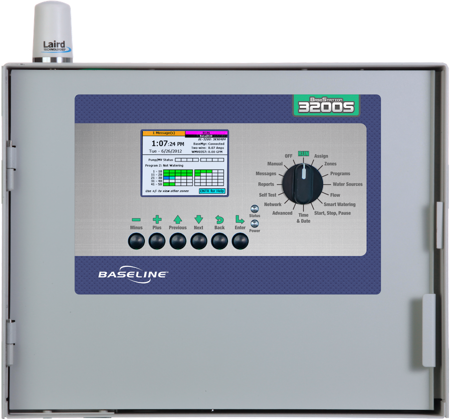
The BaseStation 3200S site management controller provides users with more control and more information than ever before. It supports the patented two-wire technology from Baseline, as well as conventional wire and retrofit solutions. Its advanced flow management features and flexible communication options allow users to network devices through the cloud or using a local area network.
The BaseStation 3200S combines soil moisture sensor-based intelligent watering technology from Baseline with the industry’s best practices for weather-based irrigation into a single user interface. The BaseStation 3200S can help you reduce water use by up to 62 percent.
Existing BaseStation 3200 controller displays, operating system, and firmware can be easily upgraded – click here for details
Register your BaseStation 3200S Controller here.
Engineered for Intelligent Site Management
The BaseStation 3200S leverages its unique responsive technology and performance components to support up to 99 concurrent zones and manage non-irrigation zones with ease.
Solving Problems in Real Time
- Real-time data means you can control what you need to when you need to
- Smart watering with moisture sensors can save up to 62 percent versus standard water methods
- Responsive flow management and data analytics gives you the ability to optimize water resources
- Dynamic central control capabilities save you time and resources
- Leak detection programming will stop leaks fast and alert you in real-time
Responsive, Real-Time Technology
Every BaseStation 3200S supports all of our responsive two-wire devices right out of the box. The strength of our two-wire solution comes from its patented, true two-way communication. This means our devices provide real-time data where you need it, when you need it.
Flow Optimization
The programming and features of the BaseStation 3200S enable you to take precise control over the water at your site. You can manage every aspect of flow starting from the water source to control point (a master valve, pump, or a hydrometer) to the mainline and down to the zone. The Baseline irrigation controller software learns the flow for each zone, maximizes the number of zones it can turn on at once, and helps shorten your water windows.
Efficient Resource Management
In order to water smart, comply with water regulations, and prevent over-watering and runoff, you also have to know when to stop irrigating. You can guess or you can measure.
Baseline soil moisture sensors measure the actual soil moisture content where it really matters — in the root zone. With average water savings of 62 percent, we can show you how to use less water while optimizing plant health. You can determine exactly how much to irrigate and when field capacity is achieved. This information allows you to start, stop, or pause irrigation programs according highly accurate data.
WeatherAccess™ for BaseManager provides a platform that combines our soil moisture sensor-based intelligent watering technology with the industry’s best practices for weather-based irrigation into a single user interface.
Get Real-Time Alerts, Messages, and Reporting
When equipped with the Multi-Carrier Modem, the BaseStation 3200S supports automatic carrier switching in the event of network disruptions. This ensures reliable communications, flexible setup, and future-proof LTE connectivity.
For sites where cellular service is not required, the BaseStation 3200S includes a built-in Ethernet port so the controller is internet-ready out of the box. Other wireless connectivity options include Wi-Fi and spread-spectrum radio.
Scale Site Management with the FlowStation and the SubStation
With the addition of a FlowStation™, you can monitor and manage water resources across as many as 20 BaseStation 3200S controllers.
Flow Management: The FlowStation maximizes the number of valves and controllers that can operate at once based on the amount of water that is available. Multiple BaseStation 3200S controllers can operate simultaneously and the FlowStation will manage which controllers get water and how much they are allowed to use.
The SubStation™ wirelessly connects to the BaseStation 3200S controller using ethernet radios or wireless network. Once networked, the BaseStation 3200S can program and run all zones and devices connected to a SubStation. Obstacles for a wire path such as roadways, water features, or buildings are easy to plan around with SubStations.
A single BaseStation 3200S can connect with up to eight SubStations, and because each SubStation has its own 24 volt transformer, the BaseStation 3200S can run up to 99 zones concurrently thus dramatically reducing water windows.
Features that Matter
- Supports up to 200 zones
- Supports two-wire and conventional wire
- Supports up to 25 soil moisture sensors
- Supports up to 99 programs
- Supports up to 8 water sources
- Supports up to 8 points-of-control
- Supports up to 8 mainlines
- Supports up to 99 concurrent zone operations
- Includes advanced flow management and monitoring features
- Uses pressure readings to start, stop, and pause management and monitoring features
- Supports weather-based watering
- Includes built-in Ethernet port
- Supports Wi-Fi, cell modem, and spread spectrum radio
- Prioritizes based on control point or program
- Supports Intelligent Water Rationing™
- Integrates with any FlowStation™ or SubStation™
- Supports controller-level tiered passcodes
- Includes detailed, on-screen instructions and help
Solutions for Your Project
The BaseStation 3200S offers irrigation features that can help you manage any landscape project you might have. New construction or retrofits, big projects or small, the BaseStation 3200 has the solution for:
- School districts
- Parks departments
- Municipal landscape departments
- College and University campuses
- Commercial properties
- High-end residential properties
- Homeowner’s Associations
- Water-harvesting projects
- LEED projects
- Building management projects
- Professional athletic stadiums
- Sports turf and playing fields
- Greenhouse and hydroponic projects
BaseStation 3200S Specifications
BaseStation 3200S Display Features
- High contrast 3.5 inch TFT LCD screen
- Screen resolution is 320×240 at 65,536 colors
- Screen brightness of 200 lumens for easy viewing in direct sunlight
BaseStation 3200S Smart Watering Modes
In addition to time-based watering, the BaseStation 3200S can also be operated in the following smart watering modes:
Soil Moisture Sensor-Based Watering
If you have a Baseline soil moisture sensor (biSensor™) installed in your landscaping and connected to your BaseStation 3200S irrigation controller, you can program the controller to water based on the moisture levels in the soil.
Weather-Based Watering
When operated in WeatherAccess™ mode with an active BaseManager™ Plus subscription, the BaseStation 3200S irrigation controller meets the EPA WaterSense program’s water-efficiency and performance criteria.
On the BaseStation 3200S, you can combine Baseline’s soil moisture sensor-based intelligent watering technology with the industry’s best practices for weather-based irrigation.
BaseStation 3200S Operating Features
- Supports up to 200 zones along a two-wire path and/or a conventional wire path
- Supports up to 25 moisture sensors
- Supports up to 8 temperature sensors, which monitor and control program operation based on temperature thresholds
- Supports up to 8 devices with contacts that alternate between open and closed (known in Baseline terminology as event switches)
- Supports up to 8 water sources
- Supports up to 8 independent mainlines for control and management of separate water delivery systems
- Supports up to 8 hydraulic components known as “control points.” The control points accept input from:
- Up to 8 normally open or normally closed master valves
- Up to 8 pump starts
- Supports up to 8 flow sensors or meters, including indoor flow sensors and hydrometers
- Up to 8 pressure biCoders, which accept 4-20 mA inputs from pressure transducer devices
- Supports up to 99 completely independent programs
- Supports up to 8 available addresses for TCP/IP-based connections. These addresses are used to connect the following performance components:
- Baseline’s FlowStation
- Baseline’s SubStation, SubStation RV, and SubStation CP
- The Munro Pump Station
- The controller supports concurrent zone operation.
- In stand-alone operation, the controller’s transformer supports a maximum of 15 concurrent zones.
- When operated in conjunction with Baseline’s SubStation, the number of concurrent zones will increase by 15 zones with each additional SubStation. With 8 SubStations, the controller supports a maximum of 99 concurrent zones.
- Over conventional wire, the controller operates up to 2 typical solenoids per 12-station powered biCoder or up to 4 typical solenoids per 24-station powered biCoder plus 2 additional solenoids using the VE00001 and VE00002 ports.
- Device Assignments
- The controller searches for and identifies all devices connected to the two-wire and lists them according to device type and serial number.
- The controller is capable of addressing or re-addressing any two-wire decoder (biCoder) from the controller by re-assigning the device’s serial number to a new zone address.
- The controller assigns any station or terminal number on a multi-station biCoder from the controller to any zone address in any order, in any program.
- The controller allows any device to be removed, replaced, or reordered.
- The controller supports full two-way communication with all devices and monitors two-wire voltage and communication integrity, solenoid voltages, current, and status (reported as open/short/OK).
- The controller monitors leakage current between the valve decoder and solenoid when bad wire-connections are present.
BaseStation 3200S Programmable Features
- Program up to 8 start times per program in 5-minute increments
- The controller automatically stacks overlapping programs.
- The controller supports program prioritization and progression to allow control of which landscape areas get watered first, and/or to prioritize water rations during restricted water allocations. Program priorities can be set from 1 – 99.
- Each program allows from 1 – 15 concurrent zones. The user can configure a program to ignore concurrent zone settings, which enables the program to run even when the maximum number of concurrent zones are running as long as the system does not exceed electrical and hydraulic limits.
- The user can configure a program to ignore global controller settings such as a rain delay, which enables the program to run even when even when the controller is in rain delay mode.
- Program the run times for zones from 1 minute to 23 hours 59 minutes
- The user can configure zone runtimes with second-level resolution.
- Program the day intervals in even days, odd days, or odd days excluding the 31st, programmable day interval
- Create a custom 7-day calendar
- Create a historical calendar with customizable half-months intervals
- Program unique soak and cycle times (Intelligent Soak Cycles™) for each zone or scheduling group. Cycle times and Soak times can be programmed between 0 minutes and 23 hours 59 minutes.
- Specify hours during each day of the week when water can or cannot be applied (Water Windows) in 1-hour increments for each 24-hour period
- Assign advanced irrigation modes (such as timed, primary, linked, soil moisture-based, or weather-based) to each zone
- Adjust seasonal water budget from 25% to 200% by program
- Schedule 8 controller-wide event dates plus 8 event dates per program during which watering is disabled
- Manually operate one zone, multiple zones, or all zones of a program with programmable concurrent zones and run times
- Manually start or stop a program
- Back up and restore all programming and historical data with any USB flash drive
- Establish 3 levels of 4-digit PIN password protection: operator, programmer, and administrator
- The controller stores all program and history information in non-volatile memory.
- Manually or automatically configure soil moisture thresholds and make irrigation decisions based on those thresholds
- Schedule soil moisture sensor calibration once, once each month, or never
- The controller allows a program to be started by the following conditions:
- Start time
- Moisture percent
- Temperature value
- Event switch contacts open/closed
- Pressure sensor readings
BaseStation 3200S Messages and Alerts
- Provides real-time soil moisture measurements and watering feedback to the user
- Includes integrated tools and software that self-diagnose problems and generate alerts and messages, and then displays the messages on the screen
- Displays an on-screen, historical-run-time chart that includes the time watered for last 6 days by program
- Displays on-screen a historical water used chart that includes the actual water used for the last 6 days by flow meter
- Displays a 6-day scalable soil moisture history graph with integrated run-time bar chart
- Displays all pause and stop conditions in message screens that are accessible from the main screen. The system displays one message for each condition, and the user can clear each message
- Displays high flow alerts, low flow alerts, pause messages and conditions, and rain delays, wire faults, as well as other operating conditions
Central Control and Remote Control
- Connect the BaseStation 3200S to BaseManager™ and LiveView™ when configured with an approved communication module.
- Manually program and operate all configured zones from BaseManager central control software
- Receive email and text message alerts when connected to BaseManager central control software
- Perform manual operations remotely with Mobile Access™ when connected to BaseManager central control software
Information Security Controls
The BaseStation 3200S includes information security controls that enable secure networking with other Baseline products.
To learn more about the BaseStation 3200S security controls, refer to the Baseline Security Controls Technical Specification.
Supported Flow Management Devices
- Up to 8 flow sensors or meters
- Flow meters are assigned to control points.
- Flow meters take flow rate readings twice per minute.
- Flow meters take water used readings once per minute.
- Up to 8 master valves
- Each master valve is assignable to any control point.
- The controller can operate normally open and normally closed master valves.
- Up to 8 pumps
- The controller can manage a pump or other loads switched with a relay on a per program basis.
- Up to 8 pressure sensors
- The controller can react to high- and low-pressure settings on the mainline with a pressure sensor.
- The controller can ramp up or down the delay between zones starting and stopping with a pressure sensor.
Supported Flow Management Components
- Up to 8 control points, to which any of the following devices can be assigned:
- Flow meter
- Master valve
- Pump
- Pressure sensor
- Up to 8 mainlines
- The controller allows a zone to be assigned to any one mainline.
- The controller supports a connection to Baseline’s FlowStation.
- The FlowStation and up to 20 BaseStation 3200S controllers become a shared flow group where water is shared and managed among all controllers.
Flow Monitoring & Management Functionality
- The controller displays real-time flow updated every 15 seconds when watering.
- The controller can learn flow for programs and sets of zones.
- The operator can perform the learn flow operation while normal irrigation continues.
- The operator can schedule learn flow cycles for individual zones or for programs during a time when the system is not irrigating.
- The controller intelligently schedules watering based on available flow or design flow to maximize concurrent valve operation and minimize total water time by mainline.
- The controller limits the number of concurrent zones using the design flow.
- The controller detects flow variance at the water source level and/or the mainline level.
- In an “overflow event,” the controller halts all irrigation on the faulty control point or on the mainline.
- The controller can dynamically allocate flow by turning on only those control points needed to supply water to a mainline with running zones.
- When a pressure sensor is associated with a control point, the controller can respond to high/low limits based on pressure readings.
- The operator can set a separate variance percentage in 4 GPM ranges.
- Flow below 25 GPM
- Flow from 25 to 100 GPM
- Flow from 100 to 300 GPM
- Flow above 300 GPM
- The operator can set delays based on time or pressure before and after running zones on a mainline.
Water Management
- The controller supports 8 water sources. A water source is assigned to a control point.
- The controller supports water source prioritization and intelligent secondary water source management to control which water sources are used first.
- The controller supports empty and full indicators from moisture sensors, switches, and pressure sensors to optimize management of cisterns, ponds, rainwater catchment, and other water storage systems.
- The controller supports a settable wait time after an empty condition is met.
- The controller supports a monthly water budget per water source. The controller can shut down the water source when the budget has been exceeded.
- The controller supports daily water rationing across multiple water sources.
Hydraulic Layout
Users can make the following connections in order to model their actual hydraulic system on the controller:
- Connect a water source to a control point
- Connect a control point to a mainline
- Assign zones to their mainlines
Electrical Specifications
Transformer Input
- Requires 120 VAC, 50 Hz to 60 Hz and a minimum of a 5 amp breaker
- Requires a certified electrician for hard-wire installation
Power Output
- Station Output: 30 VAC RMS over two-wire
- Supports up to 1.45 amp output
- The controller powers down the two-wire after one minute of idle time
- Drive current to a decoder is 100 to 250 milliamps (depending on the solenoid)
- Supports up to 110 device loads on a two-wire path
- 1, 2, and 4 station biCoders = 1/2 load
- 12 or 24 station Powered biCoders = 2 loads
- Soil Moisture Sensor = 1 load
- Flow biCoder or Flow Sensor = 3 loads
- Event device = 1 load
- Pressure biCoder = 3 loads
Solenoid Specification
- Requires a typical solenoid with approximately 400 milliamps of inrush current and approximately 200 milliamps holding current
Surge Protection
- 10 levels of surge protection
- Up to 5 levels of surge protection built into the controller boards
- Minimum surge response time of 1 picosecond
Enclosure Options
“X” Cabinet—Wall Mount Enclosure
- Dimensions: 15.50” x 12.38” x 6.40”
- 16 Gauge, powder-coated
“XS” Cabinet—Wall Mount Enclosure
- Dimensions: 15.50” x 12.38” x 6.40”
- 16 Gauge, 304-grade stainless steel
“P” Standard Pedestal Enclosure
- Dimensions: 17.38” x 36.25” x 12.63”
- 16 Gauge, 304-grade stainless steel
“PSS” Super Strong Pedestal Enclosure
- Dimensions: 16” x 38” x 15.5”
- 16 Gauge, 304-grade stainless steel
Baseline’s Communication Modules — Features and Specifications
There are multiple different connection options available for the 3200S. See the list below for a basic overview of each type. For a detailed overview of each communication solution’s specifications, visit the Design Specification and Resource Library and go to the communication module information section.
Cloud Network Module
Add a Cloud Network Module with Multi-Carrier Modem to your BaseStation irrigation controller to enable reliable remote connectivity. The Multi-Carrier Modem supports automatic carrier switching in the event of LTE network disruptions. This ensures reliable communications, flexible setup, and future-proof LTE connectivity.
When you choose a cell modem communication package from Baseline, we provide the cell modem hardware, the antenna, the SIM card from the wireless carrier, and the firmware that activates the connection from your controller.
We do not charge for cellular data.
RJ45 Ethernet Port
All Baseline controllers ship with an active RJ45 Ethernet port for direct-connect Ethernet cables. The Ethernet port allows the controller to send and receive data over an existing network at your site.
Gateway Modem
Multiple nearby controllers can be connected to the Gateway Modem using their built in Ethernet ports. This option uses 4g LTE to connect the controllers to the cloud.
How to Specify
See the Network Communications Specifier’s guide to determine which communication solution is right for your site. For technical details related to any specific communication devices, visit the Design Specifications page on Hydropoint.com/baseline.
BaseStation 3200S Documentation
Brochures & Manuals
Technical Specifications
- BaseStation 3200S Technical Specification – V19 Firmware
- BaseStation 3200 Technical Specification -V18 Firmware
- BaseStation 3200 Configuration & Specification Guide
- Central Control Technical Specification
- DC Irrigation Controller Technical Specification
- Baseline Security Controls Technical Specification
Installation Details
- 2-Wire Layout Detail for BaseStation 3200 (PDF)
- Detailed Drawing for the BaseStation 3200 in a C Cabinet (PDF)
- Detailed Drawing for Grounding a Pedestal Enclosure (PDF)
- Detailed Drawing for Grounding a Pedestal Enclosure (DWG)
- Pedestal Mounting Detail (PDF)
- Pedestal Mounting Detail (DWG)
- Detailed Drawing for Mounting an X Cabinet (PDF)
- Detailed Drawing for Mounting an X Cabinet (DWG)
- Detailed Drawing for a BaseStation 3200 in an X Cabinet (PDF)
- Detailed Drawing for the BaseStation 3200 in a Pedestal Enclosure (PDF)
- Grounding Details for Wall Mount Enclosures (PDF)
- Grounding Details for Wall Mount Enclosures (DWG)
- Detailed Drawing for Mounting a C Cabinet (PDF)
- Detailed Drawing for Mounting a C Cabinet (DWG)
- BL-XP Pedestal Base Info Sheet (PDF)
Installation Guides
General Specifications
Advanced Programming
- WeatherAccess™ Overview
- Baseline Solutions for Irrigating from a Pond or Cistern
- Baseline Solutions for Dealing with Water Restrictions
- Water Conservation Tips
- Turning Electricity On/Off with a Program
- Understanding the Benefits of Soak Cycling
- Stopping Irrigation for Rain Events
- BaseStation 3200 – Assigning Zones
- BaseStation 3200 – Setting Up Programs
- BaseStation 3200 – Setting Up Mainlines
- BaseStation 3200 – Setting Up Soil Moisture Sensors
- Enabling Weather-Based Watering on a BaseStation 3200
- BaseStation 3200 – Shutting Down Irrigation with Water Source Empty Condition
- BaseStation 3200 – Configuring Lower Threshold Moisture Sensor-based Watering
- BaseStation 3200 – Upper Threshold Moisture Sensor-based Watering
- BaseStation 3200 – Run More than One Zone at a Time
- BaseStation 3200 – Configuring Zones
- BaseStation 3200 – Setting Up Points of Connection
- BaseStation 3200 – Learning Flow
- BaseStation 3200 – Setting Up Start, Stop, Pause Conditions
Supporting Documents
- BaseStation 3200 User Manual -V17 Firmware
- BaseStation 3200 Quick Start Guide -V17 Firmware
- BaseStation 3200 Remote Display Instructions
- BaseStation 3200 Shortcuts
- BaseStation 3200 Upgrade Label for C Series Controllers
- BaseStation 3200 Upgrade Label for X & P Series Controllers
- BaseStation 3200 Upgrade Overlay Labels
- Connecting a BaseStation 3200 Irrigation Controller to a Munro Pump Station
- BaseStation 3200 – Updating the Firmware from BaseManager
- BaseStation 3200 – Updating to the V17 Firmware from a USB Drive
- Update BaseStation 3200 Firmware & Labels – Option #1
- Update BaseStation 3200 Firmware & Labels – Option #2A
- Update BaseStation 3200 Firmware & Labels – Option #2B
- Update BaseStation 3200 Firmware & Labels – Option #3
Legacy Documents
Technical Specifications
General Specifications
Supporting Documents
Communication Modules Documentation
Specification Documents
Installation Guides
Support Documentation
How to Specify the BaseStation 3200S Irrigation Controller
1. Start with the Controller Part Number:
BaseStation 3200S Controller
Part Number: BL-3200
- Large, full color LCD screen
- Intuitive dial positions and buttons
- Manage up to 200 zones
- Use up to 25 soil moisture sensors
- Incorporate 8 master valves
- 8 flow sensors
- 99 programs
2. Then, Choose an Enclosure Option:
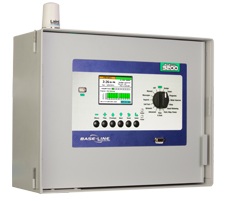
“X” Series Enclosure
- Large metal wall mount enclosure
- 15.50”W x 12.38”H x 6.40”D
- Available in 16-gauge steel, powder coated (X) & 16-gauge, 304-grade stainless steel (XS)
- Interior/exterior mount
- Compatible with R-Series Powered biCoders – holds up to 48 conventionally wired zones
- Compatible with any communication module
How to Specify: BL-3200X or BL-3200XS
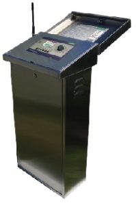
“P” Series Pedestals
- Standard stainless steel pedestal enclosure
- 17.38”W x 36.25”H x 12.63”D
- 16-gauge, 304-grade stainless steel
- Compatible with R-Series Powered biCoders – holds up to 48 conventionally wired zones
- Compatible with any communication module
How to specify: BL-3200P
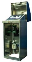
“PSS” Series Pedestals
- Super strong stainless steel pedestal enclosure
- 16”W x 38”H x 15.5”D
- 16-gauge, 304-grade stainless steel
- Compatible with R-Series Powered biCoders – holds up to 48 conventionally wired zones
- Compatible with any communication module
- Has a stainless steel cam style lock mounted in the lid and a provision for a padlock included within the locking mechanism.
How to specify: BL-3200PSS
3. Specify Two-Wire or Conventional Wire
Every BaseStation 3200S controller is two-wire ready. Any BaseStation 3200S controller can work with a conventional wire site with Baseline Powered biCoders. Add up to 48 conventional wire terminal stations to any BaseStation 3200S. Baseline Powered biCoders are available in 12 and 24 station configurations. Specify the conventional wire station count by adding “-R12”, “-R24”, “-R36”, “-R48” to any BaseStation 3200S part number.
How to Specify: BL-3200X-R48
Every BaseStation 3200S is capable of controlling up to 200 zones in any combination of two-wire and conventional wire. Combine multiple existing small-station-count controllers into one controller by replacing one of the old controllers with a BaseStation 3200 and one or more old controllers with Powered biCoders (BL-5200X or BL-5200C) in their own enclosures.
Note: Each BL-5200 Powered biCoder must be connected to a BaseStation 3200 with a two-wire path. Please see the Two-Wire Specification for wire specifications.
4. Next, Choose a Communication Option
See the Network Communications Specifier’s guide to determine which communication solution is right for your site. For technical details related to any specific communication devices, visit the Design Specifications page on Hydropoint.com/baseline and go to the communication module information section.
Baseline’s Communication Modules
There are multiple different connection options available for the 3200S. See the list below for a basic overview of each type. For a detailed overview of each communication solution’s specifications, visit the Design Specification and Resource Library and go to the communication module information section.
Cloud Network Module
Add a Cloud Network Module with Multi-Carrier Modem to your BaseStation irrigation controller to enable reliable remote connectivity. The Multi-Carrier Modem supports automatic carrier switching in the event of LTE network disruptions. This ensures reliable communications, flexible setup, and future-proof LTE connectivity.
When you choose a cell modem communication package from Baseline, we provide the cell modem hardware, the antenna, the SIM card from the wireless carrier, and the firmware that activates the connection from your controller.
We do not charge for cellular data.
RJ45 Ethernet Port
All Baseline controllers ship with an active RJ45 Ethernet port for direct-connect Ethernet cables. The Ethernet port allows the controller to send and receive data over an existing network at your site.
Gateway Modem
Multiple nearby controllers can be connected to the Gateway Modem using their built in Ethernet ports. This option uses 4g LTE to connect the controllers to the cloud.
How to Specify
See the Network Communications Specifier’s guide to determine which communication solution is right for your site. For technical details related to any specific communication devices, visit the Design Specifications page on Hydropoint.com/baseline.